1. Introduction
With the rapid development of the jewelry industry chain, the materials of the metal jewelry chain have become increasingly diverse, covering a wide range of materials such as gold, K gold, silver, and copper alloys, with a wide variety of product forms. However, in real wearing scenarios, jewelry chains often break or loosen due to unexpected tension, which not only seriously affects user experience but may also cause safety hazards such as swallowing due to parts falling off, posing a threat to consumers' health and life.
Therefore, it is especially crucial to use scientific methods to accurately assess the mechanical properties of jewelry chains. As a core testing method, tensile testing can accurately simulate the true performance of jewelry chains under stress, providing reliable data support for manufacturers to select high-strength raw materials, optimize welding and fastening processes, and conduct rigorous factory inspections of finished products. It is an indispensable technical foundation for ensuring product quality and safety.
2. Testing Principles and Key Mechanical Indicators
1. Testing principle
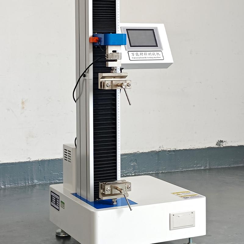
The core principle of the metal jewelry chain tensile test is to apply a continuous, constant tensile load along the longitudinal main axis of the sample until the sample breaks or reaches a preset percentage. Throughout the entire testing process, the tensile testing machine is equipped with a high-precision force sensor and displacement measurement system, which records the load the specimen bears and its corresponding elongation changes in real time and continuously to generate a complete force-displacement curve. The key to this principle lies in "constant speed" and "centering"—the tensile speed must be uniform and impact-free, and the longitudinal axis of the specimen must strictly coincide with the tensile centerline to ensure the test results can truthfully and repeatedly reflect the mechanical response behavior of jewelry chains under unidirectional tensile stress.
2. Maximum force
Maximum force refers to the maximum force the specimen experiences throughout the entire tensile test process, usually expressed in newtons. For metal jewelry chains, this indicator directly reflects their overall ultimate tensile strength and is one of the most direct and core parameters for evaluating product quality. In actual tests, the maximum force may correspond to the moment when a chain link is snapped, or it may be the moment when weak points such as connectors or welds fail. By measuring maximum strength, companies can horizontally compare the strength advantages of jewelry chains made from different materials (such as 18K gold and pure gold), different chain types (such as snake bone chains and box chains), or different processes (such as laser welding and thermal welding), providing quantitative support for product design and process improvement.
3. Specify elongation force
Specified elongation refers to the force value corresponding when the elongation of the gauge section of the specimen reaches a specified percentage (e.g., 0.5%), usually denoted as Fp0.5. This indicator is mainly used to characterize the resistance characteristics of jewelry chain materials during the transition stage from elastic deformation to plastic deformation. Unlike maximum force reflecting "ultimate strength," the elongation requirement focuses more on assessing the rigidity of the jewelry chain under low stress—that is, under what tensile force it will begin to develop irreversible permanent deformation. For chains that require shape stability (such as decorative chains with fine patterns), the higher the elongation, the less likely they are to be stretched or deformed during normal wear, thus maintaining their original appearance and size.
4. Fracture phenomena and fracture analysis
Fracture refers to the phenomenon where a specimen completely separates during the tensile process, which is a typical endpoint of a tensile test. However, the information contained in the fracture phenomenon itself goes far beyond a "terminal signal"—the exact location of the fracture, the shape of the fracture, and whether there is a noticeable necking or chain link opening before the break, all provide important clues for analyzing the weak links in the jewelry chain. For example, if a fracture occurs very close to the clamp jaw (usually less than 5% of the original gauge width), it may indicate stress concentration at the fixture or improper specimen clamping, and this data is generally considered invalid. Conversely, if the fracture occurs at the chain body position within the gauge distance, the failure mode can be determined based on the fracture morphology: base material tearing, weld joint cracking, or chain link hook detachment, thereby guiding targeted process improvements.
3. Selection of tensile testing machines
1. Equipment precision requirements
The accuracy grade of the tensile testing machine is the foundation for ensuring the authenticity and validity of test data. According to the specifications for mechanical performance testing of metal jewelry chains, the testing machine should reach Grade 1 or better, meaning the force measurement error must be controlled within ±1%. High-precision ratings alone are not enough; during testing, it is also necessary to ensure that the measured force value falls within the effective range of 10%~90% of the equipment's range—this requirement avoids nonlinear errors at both ends of the measurement. Specifically, if the range is too large and the specimen experiences very little force (for example, testing an ultra-fine chain requiring only a dozen newtons), the force value will fall below the 10% lower limit, significantly reducing measurement accuracy; Conversely, if the specimen is subjected to force close to or exceeds the upper limit of the range, the sensor may be damaged. Therefore, in actual testing, sensor ranges should be reasonably selected based on the estimated sample failure load, so that the peak force of each test is as close to the 20%~80% golden range of the range as possible.
2. Range and sensor selection
The stress characteristics of metal jewelry chains differ significantly from those of other metal materials (such as construction rebar)—the breaking load of most jewelry chains and their accessories is usually between tens to several hundred newtons, much less than the full-scale range of conventional universal testing machines. To address this feature, it is recommended to select sensors with small ranges and high precision, generally using 100N~2000N as the common range. For example, a standard 18K gold necklace may have a maximum force in the range of 150N~300N, and using a sensor with a 500N range can achieve good resolution. For more precise application scenarios, such as testing micro chains with diameters below 0.2mm, elastic fasteners, or small safety chains in children's jewelry, conventional small-range sensors may still have insufficient resolution. In such cases, ultra-low range sensors of 10N~50N can be further configured. This downward range sinking strategy can significantly enhance the ability to capture minute force changes, ensuring complete data collection details.
3. Drive and control capabilities
The tension test for jewelry chains sets clear requirements for controlling the loading process: the stretch must be at a constant speed, uniform, and without impact. To achieve this goal, modern tensile testing machines commonly use servo drive systems. Servo motors combined with high-precision ball screws can provide smooth power output across the entire travel range, avoiding false force spikes caused by speed fluctuations or starting shocks, which often interfere with accurate early judgments of specified elongation and other indicators. Moreover, testing speeds vary greatly among specimens—finished chains and semi-finished chains require speeds not exceeding 300mm/min, while small components like buckles and rings require speeds not exceeding 10mm/min, and some fine tests may even require as low as 1mm/min. Therefore, the speed adjustment range of the testing machine should cover 0.01mm/min~500mm/min, enabling high-speed breakage tests of conventional chains to improve efficiency, and also allowing slow loading of small fasteners at extremely low speeds, ensuring that the force values are highly consistent with the actual force conditions.
4. Data collection and software functions
Hardware performance is inseparable from the support of supporting software. High-performance tensile testing machines should be equipped with a high-sampling data acquisition system capable of recording the correspondence between force values and displacement/time in real time at tens or even hundreds of times per second throughout the entire testing process, thus fully sketching every detail of the extensive-displacement curve—from the initial elastic section to the yield platform, then to the strengthening stage and finally to fracture. Based on this raw data, the software should be able to automatically calculate key indicators, including maximum force, specified elongation (such as Fp0.5), and elongation after break, without the need for manual curve reading or manual interpolation, which improves efficiency and eliminates human error. Furthermore, mature testing software should also support batch statistical functions for multiple sets of data—automatically calculating statistics such as mean and standard deviation from test results of multiple samples in the same batch, and generating standardized test reports containing complete information such as curve charts, data tables, and test conditions, making it easier for quality management personnel to conduct trend analysis and process traceability.

4. Configuration of specialized fixtures/auxiliary devices
1. Finished product chain testing fixture
Finished chains are recommended to use pin-type connecting accessories, where both ends of the chain are fitted onto two pins of different diameters. The pin diameter is generally chosen based on the chain ring aperture between 5mm and 25mm. The main purpose is to prevent direct contact between fasteners and snap buttons and fixtures, which can cause stress concentration. The advantages of this method are that it poses no risk of pinch damage to the specimen, is easy to assemble and remove, and its force-bearing method closely resembles the free hanging state of the jewelry chain when actually worn.
2. Semi-finished chain product testing fixture
Semi-finished chain products use flat-push gripping aids, and rubber or polyurethane cushioning pads must be added at the jaws. The cushion pad serves two purposes: first, to prevent direct contact with the metal chuck that could cause scratches or pre-deformation on the specimen surface; second, to increase the friction coefficient to avoid slipping during stretching. The initial distance between the two jaws is the original gauge distance. Before clamping, the specimen should be slightly tightened to ensure its longitudinal axis coincides with the tensile centerline.
3. Small accessory testing fixtures such as buckles and rings
For micro-samples such as couplers and rings, small pin-type connecting aids are used, with pin diameters typically 0.5mm~1.5mm. During testing, both ends (or sides) of the buckle or ring are hung on pins for stretching, mainly to assess its pull-off resistance—that is, whether the accessory will come loose, deform, or break under stress.
4. Principles for Fixture Selection
Regardless of the type of fixture used, three basic principles must be met: first, it must effectively prevent the specimen from slipping relative to the fixture; Second, as tensile load increases, the fixture should maintain or enhance the clamping force on the specimen; Third, it is essential to avoid premature failure of the specimen at the fixture due to improper fixture design; otherwise, the test results will not reflect the true strength of the specimen body.

5. Typical Testing Methods
1. Overall strength testing of the finished product chain
Finished chain testing uses the complete jewelry chain as a sample, and during sampling, mechanical damage such as stretching, twisting, or bending of the chain must be avoided. The clamping uses pin-type auxiliary hanging to ensure the chain hangs naturally and smoothly without entanglement, so the stress is close to actual wearing conditions. The test speed should be kept within 300mm/min, with the break test as the endpoint—the test stops when the chain body is pulled to the point of breaking, or when clasps, snaps, and other connecting accessories deform and cause the entire chain to separate. Key parameters to be recorded include: maximum force value, the exact location of fracture, and the fracture mode (such as chain link pulling, weld joint cracking, fastener detachment, etc.).
2. Tensile testing of semi-finished chain products
Semi-finished chain products require a certain length to be cut as a sample, with the total length greater than the original gauge length plus twice the clamping length, which is usually 80mm or 100mm. Clamping uses a flat-push gripping aid; the specimen is slightly tightened before clamping to ensure its longitudinal axis strictly aligns with the tensile centerline, and the testing speed should not exceed 300mm/min. Depending on the test purpose, a break test can be conducted to measure the maximum force, or an elongation test can be conducted—when the elongation of the gauge distance reaches a specified percentage (e.g., 0.5%), the specified elongation force is taken.
3. Tensile testing of small accessories such as buckles and rings
Small components such as couplers and rings are taken individually as specimens and hung using small pin-type connecting aids. Pre-deformation of the coupler's structure must be avoided during clamping. Because these accessories are small and sensitive to force, the testing speed should be controlled within 10mm/min, and low-speed loading helps more accurately reflect their static tensile strength. The key points of observation are: whether the fastener has come loose, whether there is obvious deformation, and whether there is fracture or failure.
6. Factors Influencing Test Results and Controls
1. Environmental condition control
The test environment directly affects the stability of test results. The temperature should be controlled between 10°C and 35°C, and the environment should be free of corrosive gases to avoid adverse effects on sample materials or equipment. In addition, the test bench must remain level and have sufficient operating space to ensure the machine runs without interference and the stretching process proceeds smoothly.
2. Representativeness of the sample
To ensure the test results are statistically significant, at least two identical samples should be taken for parallel testing whenever possible. Special care must be taken during sampling to avoid mechanical damage such as tensile, twisting, or bending of the sample, as this may introduce additional initial stress or defects, causing test values to deviate from the true level.
3. Common ineffective outcomes and prevention
In actual testing, three common types of invalid results may occur. The first type is slipping—that is, the sample slips inside the fixture. In this case, the wear of the fixture's cushioning pad should be checked, and the initial clamping force should be appropriately increased. The second type is fracture at the jaw—if the fracture is too close to the jaw (less than 5% of the original gauge distance), it indicates stress concentration at the fixture area. This data is invalid, so the fixture design should be optimized or the clamping method adjusted to ensure more uniform force distribution. The third category is excessive elongation deviation—the deviation between the actual elongation and the target value must not exceed 1%. Otherwise, it is necessary to recheck whether there are errors in the clamping position and measurement process.
4. Data representation
All valid test results are recorded and reported, with maximum force and specified elongation force rounded to one decimal place, and labeled in newtons. Unified numerical representation rules help with data comparison and quality traceability.
7. Application Cases and Common Issues
1. Typical application scenarios
Tensile testing has broad practical applications in the field of metal jewelry chains. First, it can be used for strength comparison testing of different chain types such as gold and K gold printed chains, box chains, and snake bone chains, helping companies select chain structures that balance aesthetics and durability. Second, it can be used to evaluate the impact of different welding processes (such as laser welding and pyrowel welding) on the strength of chain link connections, providing a quantitative basis for process optimization. Third, in children's accessory safety testing, it can be used to verify the pull-off resistance of safety chain buckles, ensuring the product meets safety standards and preventing accidental swallowing risks caused by small parts falling off.
2. Common Issues and Countermeasures
Question 1:Soft gold chains are prone to slipping in flat-pushing fixtures. This is because gold is softer and has a lower coefficient of surface friction. The solution is to increase the friction coefficient of the cushion pad (such as replacing it with a rougher rubber material) or directly switch to a pin-type hanging method to fundamentally avoid slippage during clamping.
Question 2:The force values fluctuate significantly during testing of tiny couplers. This is because the coupler is small and sensitive to force, so the force values are not stable at conventional test speeds. The solution is to reduce the testing speed to 5mm/min and select high-sensitivity small-range sensors (such as 10N~50N) to improve data acquisition stability and resolution.
Question 3:The fracture always appears near the jaw. This indicates that the sample has a significant stress concentration at the fixture area, failing to reflect the true strength of the chain itself. Countermeasures include: checking and adjusting the coaxiality of the fixture to ensure good alignment between the upper and lower fixtures; Appropriately increase the original gauge length of the specimen so that the fracture surface more easily falls within the gauge range; Alternatively, transition connectors can be used to improve the force distribution at the sample ends.